Overview
In this project, I extended the functionalities of my last ray tracing rendering pipeline by adding support for rendering models with materials, rendering with environment lights, controlling aperture size and focal length of the camera for depth of field effects, and rendering in real time with basic GLSL shaders. Specifically, I added support for rendering glass and mirror materials by implementing their bsdf, and I added support for rendering custom materials by implementing microfacet materials.
Part 1: Mirror and Glass Materials
An rendering engine is much more powerful if it supports more materials that it can render. In part 1, I added support for mirror and glass materials. Below is a sequence of images of rendered with varying max depth to bounce for ray tracing, with at least 64 samples per pixel and 4 samples per light, on a scene with both glass and mirror materials.
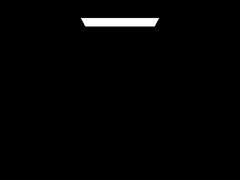
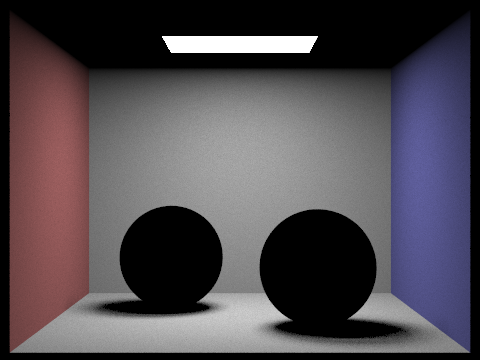
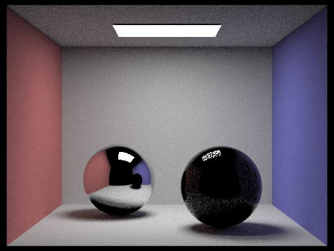
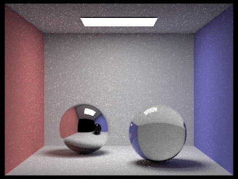
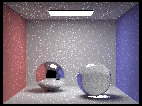
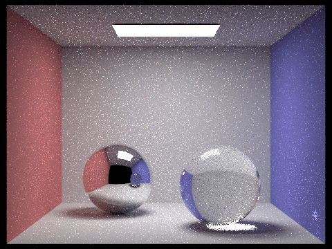
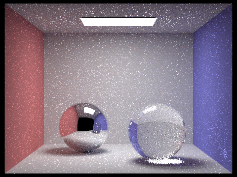
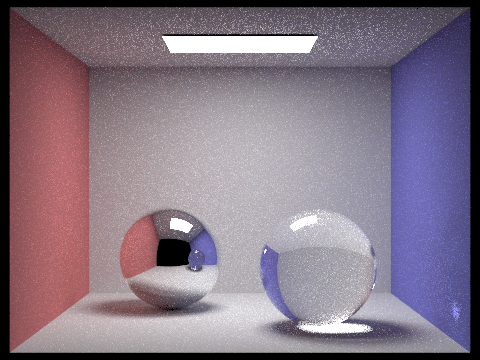
As we can see, there is clear multibounce effects. When max ray depth is 0, we effectively only have light emissions. When max ray depth is 1, the light has lightened up the walls but the balls and the ceilings are still black because the light hasn't reflected or refracted to render them yet. When max ray depth is 2, we see the the ceilings and the mirror ball have been rendered a bit as well as the highlight reflection on the glass ball is also rendered a bit. When max ray depth is 3, both balls have been relatively rendered as light is able to also refract through the glass ball, but notice how the glass ball on the right still doesn't have bright light in the shadows. The shadow for glass ball only shows bright lights refracted from the ceiling lights at the max ray depth of 4, and the highlight reflected to the right wall at the bottom corner shows up at max ray depth of 5. As we keep increasing the max ray depth, the changes are less obvious but converges to a less noisy picture.
Part 2: Microfacet Material
An rendering engine is much more powerful if it supports more materials that it can render. In part 1, I added support for microfacet materials. Below is a sequence of images of microfacet materials rendered with different roughness of macro surface for a gold dragon, rendered at least 128 samples per pixel, 1 samples per light, and at most 5 bounces.
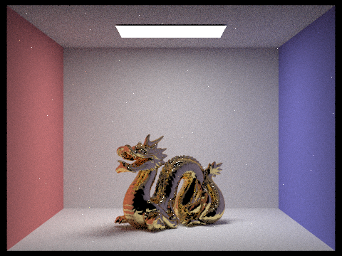
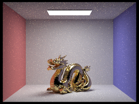
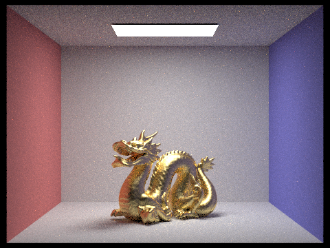
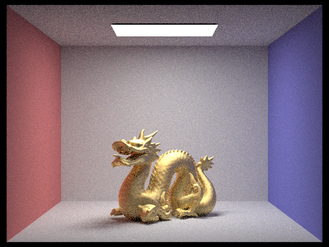
As we can see, as we increase the roughness of the macro surface, the dragon looks less and less reflective and are smoother. The color of the dragon also has fewer contrasting surface colors and reflections, and it looks more evenly spread out like a diffused material.
Below is a sequence of images rendered using cosine hemisphere sampling and importance sampling, at a fixed sampling rate of 64 samples per pixel, 1 samples per light, and at least 5 bounces.
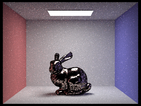
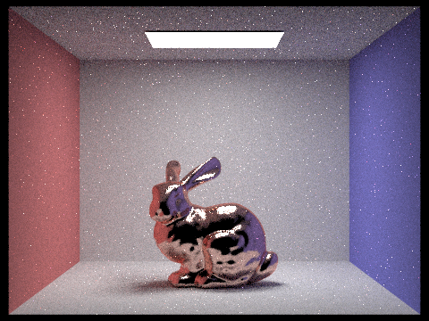
As we can see, the cosine hemisphere sampling produces a much more noisy result with lots of black spots all over the place, but the importance sampling produces a well-lit rendering at reasonably well rendered material detail, such as reflections. The importance sampling also produces much less noise.
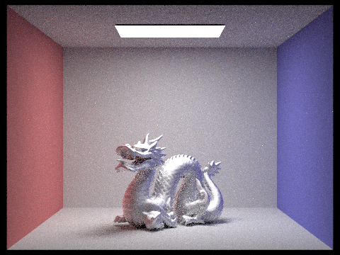
In this implementation, I added support for microfacet material, so we can also customize the conductor material of any model. It's pretty powerful. For example, below is an image of an aluminum dragon instead:
Part 3: Environment Light
We can also render models in specific environment where the material itself is rendered based on an environment given. A new type of light source is given: an infinite environment light, which supplies incident radiance from all directions. Specifically, the source is thought to be "infinitely far away" and is representative of realistic lighting environments in the real world.
Rendering using environment lighting can be quite striking. For example, we can render objects in an environment like this:
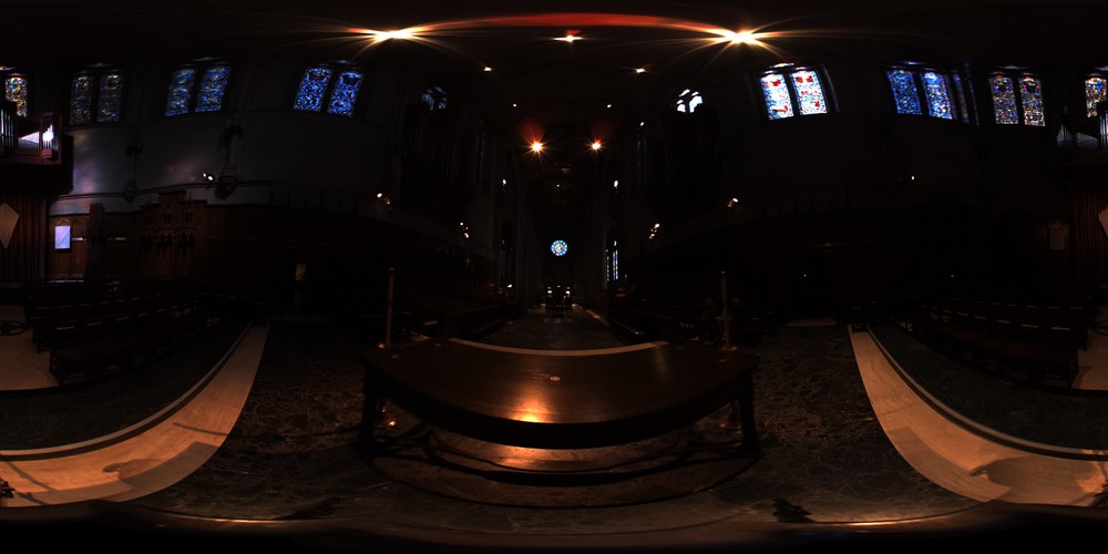
Much like light in the real world, most of the energy provided by an environment light source is concentrated in the directions toward bright light sources. Therefore, it makes sense to bias selection of sampled directions towards the directions for which incoming radiance is the greatest.
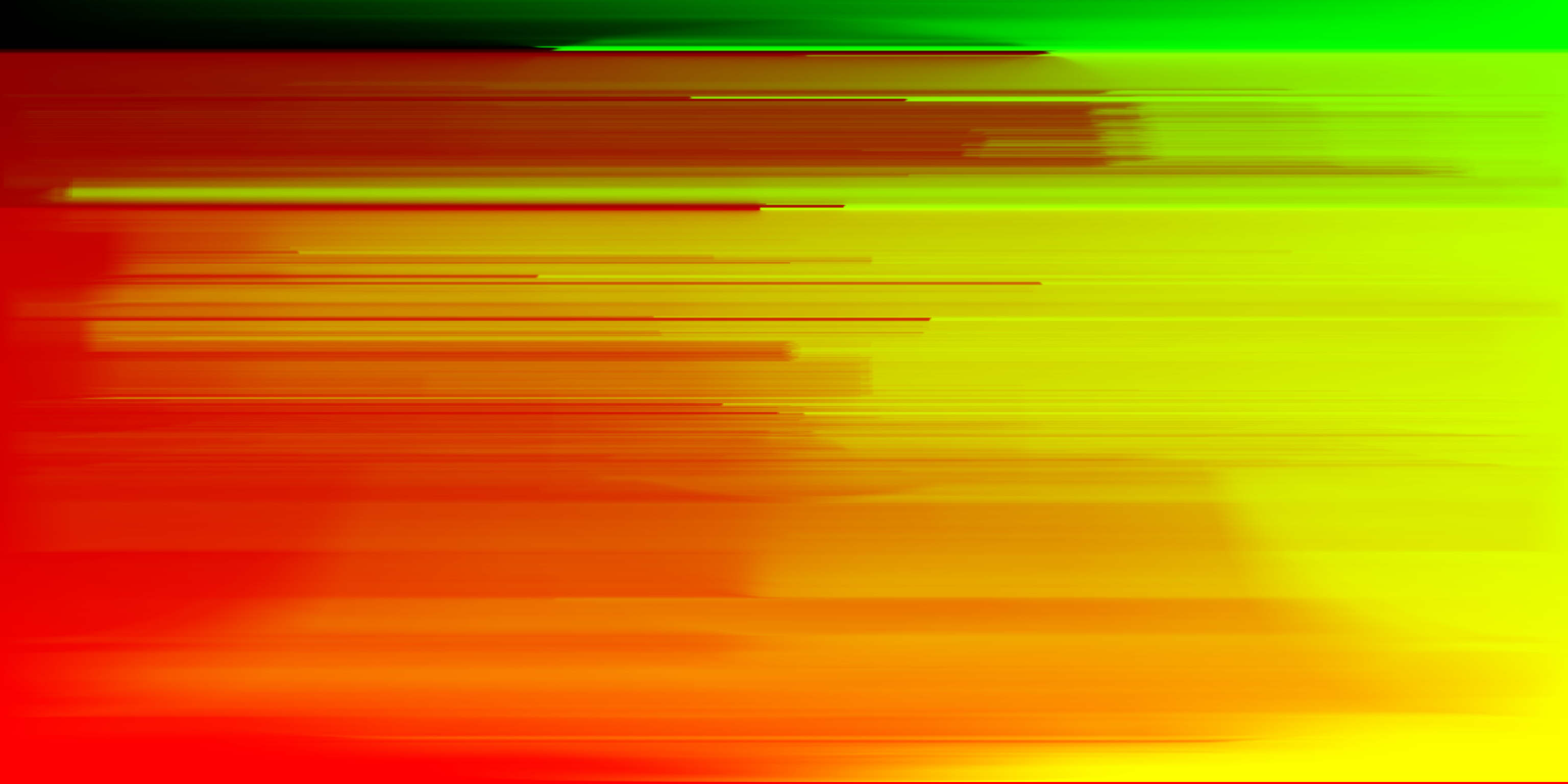
Therefore, the basic idea of rendering environment map lights is that we will assign a probability to each pixel in the environment map based on the total flux passing through the solid angle it represents. This will be our strategy for sampling the environment map based distribution. Specifically, the probability distribution for which we will sample from for the environment shown above is calculated to be as follows:
Below is a rendering of diffused bunny in the environment, rendered with 4 samples per pixel and 64 samples per light in each.
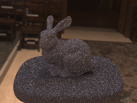
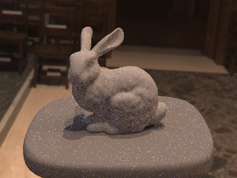
As we can see, there's a lot of noise for uniform sampling and the object looks barely visible or rendered clearly, but the importance sampling gives us a much well rendered result, despite noise.
Below is a rendering of bunny with copper microfacet material in the environment, rendered with 4 samples per pixel and 64 samples per light in each.
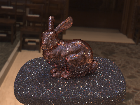
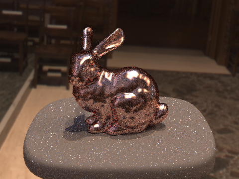
As we can see, there's a lot of noise for uniform sampling still and the importance sampling still gives us a much well rendered result, despite noise. Therefore, it seems that importance sampling outperforms uniform sampling regardless of whether it's microfacet materials.
Part 4: Depth of Field
In this part, I am going to simulate a thin lens to enable the depth of field effect for my rendering. I do so by modeling my ray generation for cameras as a pinhole camera model.
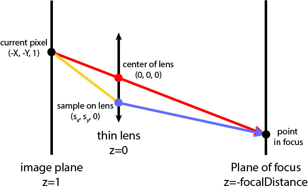
Below is a sequence of "focus stack" at 4 visibly different depths through the scene. We do so by changing our focal length of the camera.
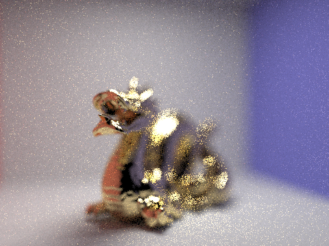
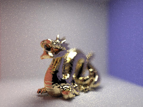
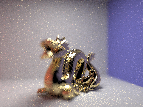
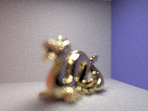
As we can see, when we increase the focal length, the image focuses on different parts of the rendering image. Specifically, because the dragon is positioned diagonally through the scene, as we increase the focal length, the camera focus moves from the head of dragon to its tail.
Below is a sequence of pictures with visibly different aperture sizes, all focused at the same point in a scene. We do so by changing our aperture size of the camera.
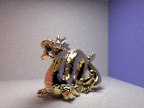
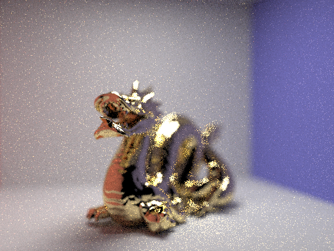
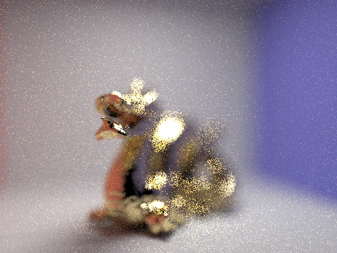
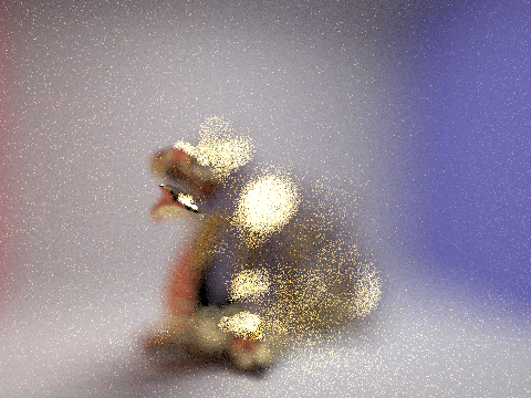
As we can see from above, as we increase the size of the aperture, the background becomes blurrier and blurrier, but the tip of the dragon's mouth is kept in focus.
Part 5: Shading
For this section, you can view a LIVE demo of real time rendering here.
In previous parts, we've been doing all of our computation on CPU. One major issue is that we have to wait several minutes to render a single frame with any realistic lighting, even with threading. However, for real-time and interactive applications like gaming, which often have framerates of 60fps, this is just impossibly slow.
Therefore, in this part, I will explore how things may be accelerated by writing a few basic GLSL shader programs.
In a high level, a shader program is an isolated program that runs in parallel on GPU, so it's very fast. A shader program describes a set of relevant operation on a single vertex, or fragment. The vertex shader manipulates the attributes of vertices (e.g. points on the geometry), and the fragment shader computes attributes such as colors and textures for each pixel, either through sampling or interpolations between vertices.
By combining vertex and fragments, we can render 3D modles with lighting, shadows, and materials.
Here I implement the Blinn-Phong shading model, which renders through three components: ambient, diffuse, and specular components. Ambient shading is the shading that doesn't depend on anything. It simply adds constant color to account for disregarded illumination and fill in black shadows. The diffuse shading factors in light, color, power and attenuation under the effects of light reflection etc. for the rendering. The specular shading captures reflections on surfaces (e.g. highlights) facing the viewer. By combing these three components, the Blinn-Phong model produces realistically rendering.

Below demonstrates the idea and effects of the Blinn-Phong shader model:

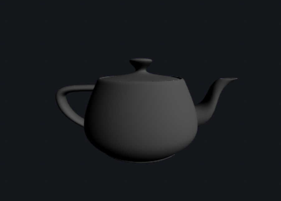
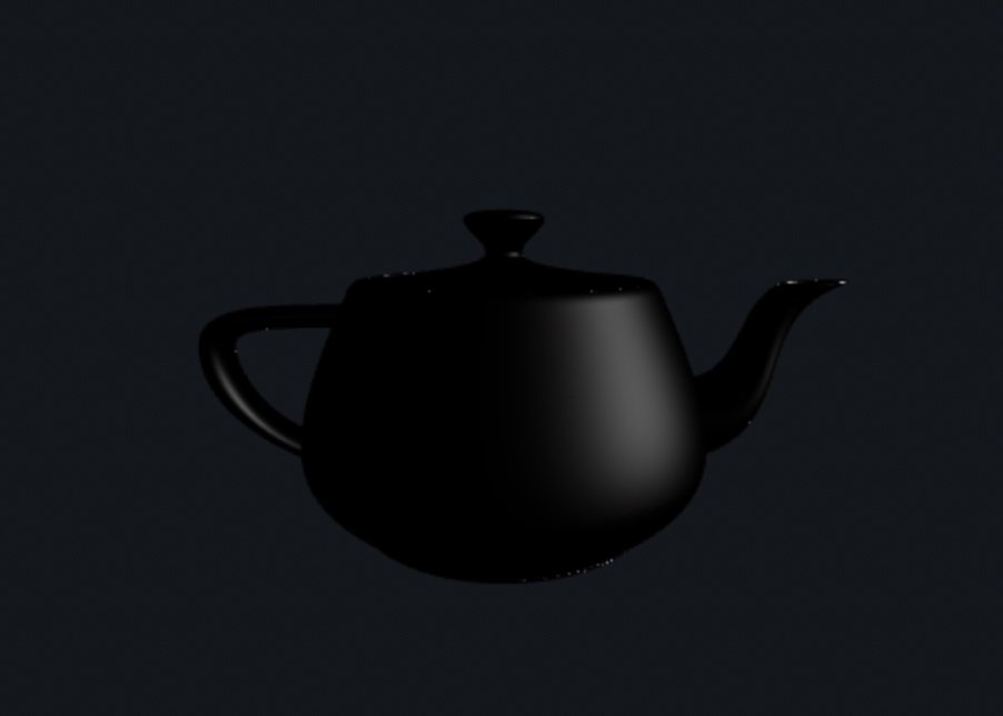
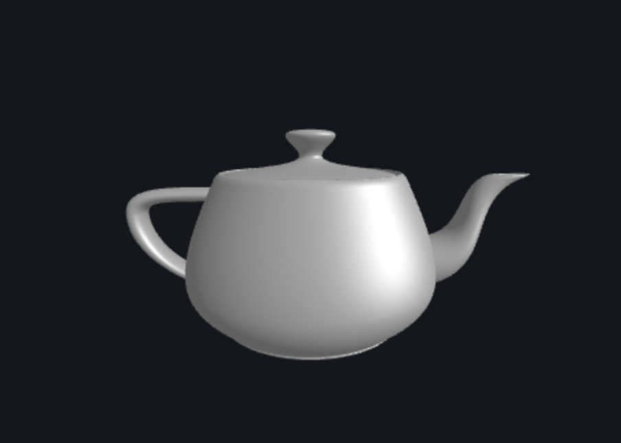
As you can see, the Blinn-Phong model captures different information about the rendering and the combined result is pretty amazing.
We can also add custom textures to the model. Note, for the rest of the demo, I will use the following two textures:
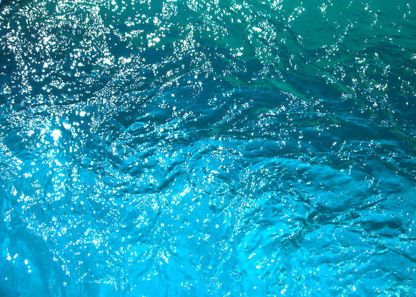
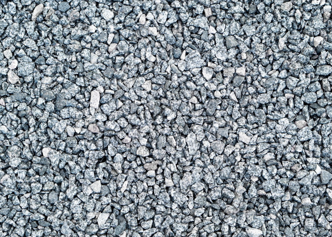
Below is a rendered sphere with water-like surface:
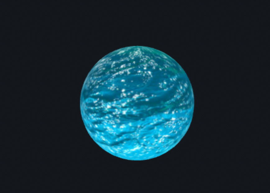
We can use textures for more than just determining the color on a mesh. With displacement and bump mapping, we can encode a height map in a texture to be processed and applied by a shader program in order to produce more complicated geometry.
Below shows the bump mapping and displacement mapping of a sphere using the stone texture:
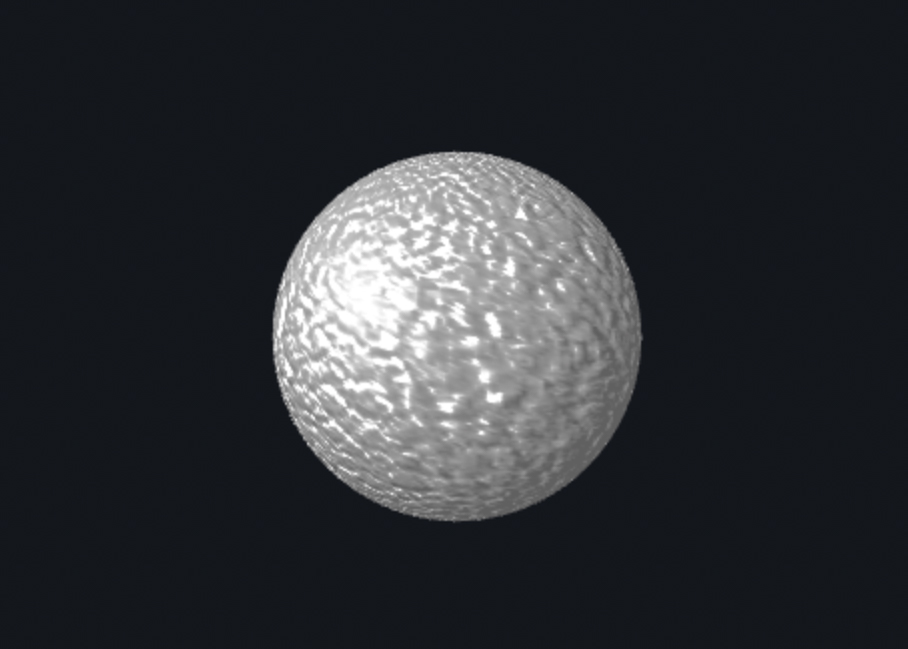
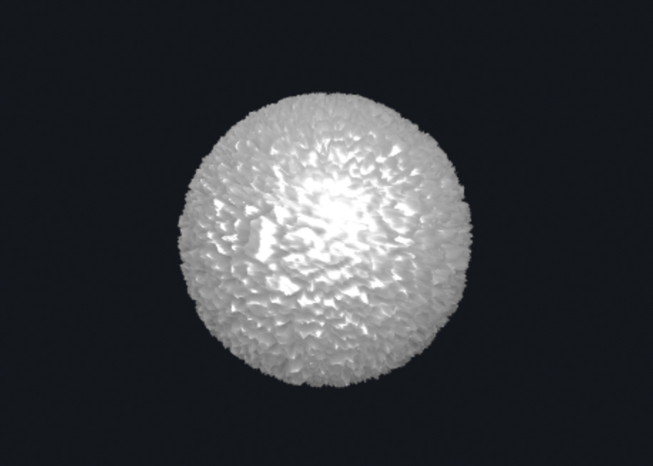
Bump mapping manipulates surface normals so the surface looks a lot more rough and uneven. Displacement mapping manipulates both surface normals and vertex positions so we can achieve effects that make the sphere surface have even larger variations. Specifically for the rendering of stone balls as shown above, bump mapping makes the ball look more rigid, and with clever parameter combination, the displacement mapping can make the ball even look more rigid, or appear fluffy and soft.
We can also change the mesh coarseness by modifying the number of vertical and horizontal components for each model to achieve different material effects. Below are some examples:
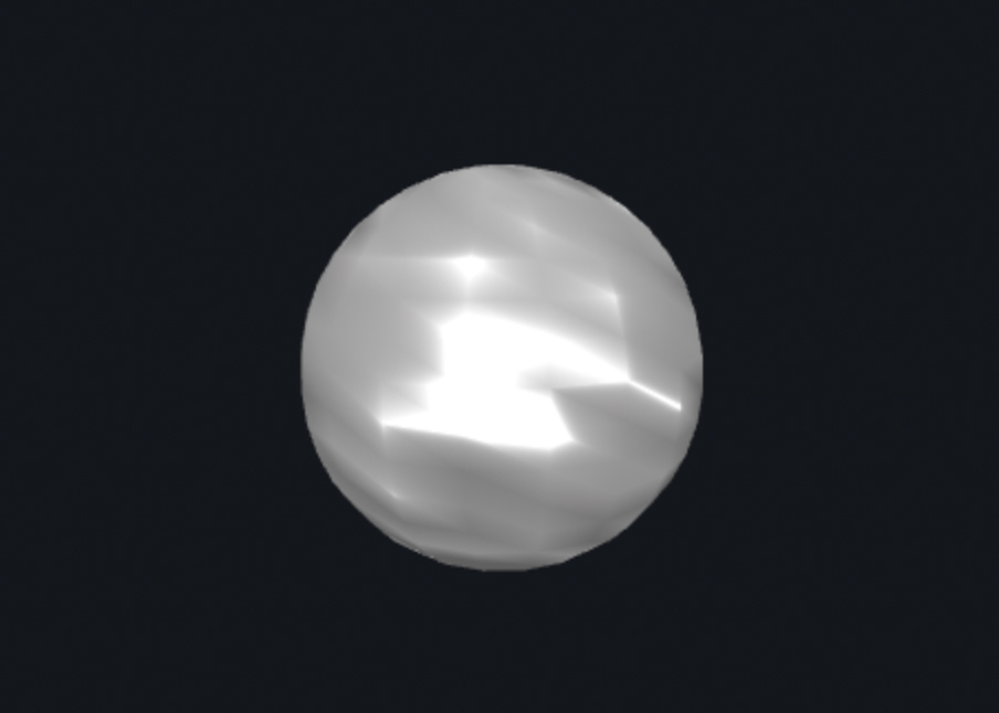
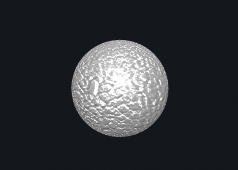
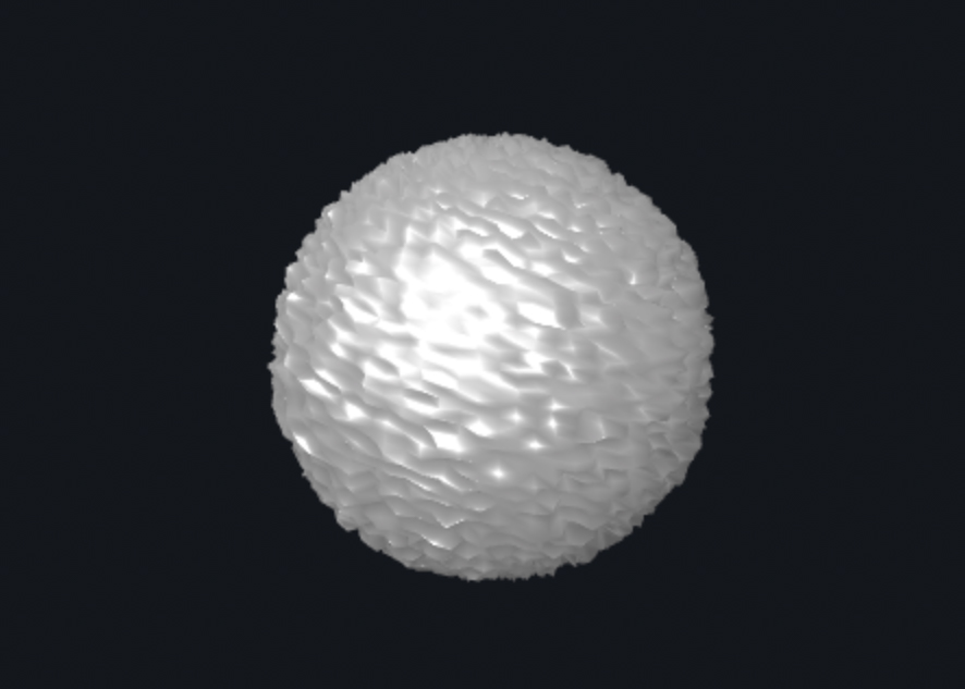
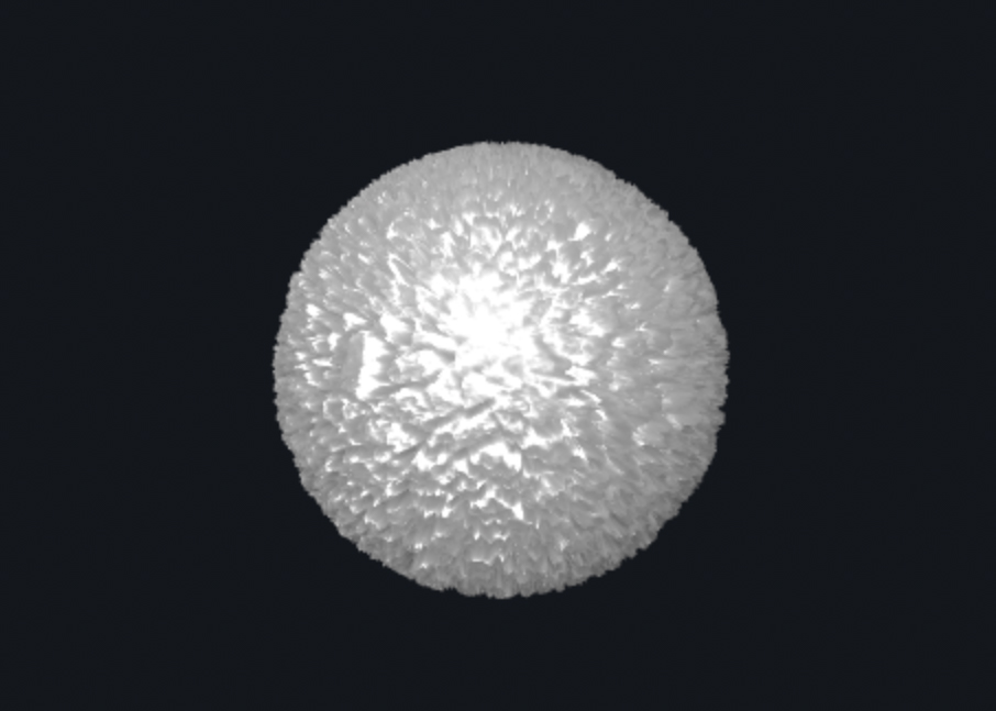
As we can see, with a smaller mesh coarseness, rendered objects generally look smoother and with a higher mesh coarseness, the rendered object are much more rough as expected. The resulting rendering can look very different given different mesh coarseness settings as well.
Lastly but not the least, I made a custom shader that produces a moving vibrating Torus Knot. It is a torus geometry with a color-changing shading material. The image doesn't do it's fun justice, so feel free to take a look live.

